Page 28 of 42 FirstFirst ... 18262728293038 ... LastLast
Results 271 to 280 of 411

Thread: DNA Development Blog

  1. #271
    Insider new ion?'s Avatar
    Join Date
    Feb 2013
    Location
    Victoria, BC
    Posts
    1,296
    Quote Originally Posted by PBSteve View Post
    If people still ran their tanks bottom line style with an integrated tank reg, this would be cool to see on guns. I don't think it would fly in the current market, though. With the move to gas-thru you'd have to standardize the ASA to frame interface, and I don't see that happening.

    For a one-off, though, I don't think it'd be difficult at all to put a transducer in the 1/8" NPT port that the tank gauge is sitting in right now. The constraint would be whether or not you can find one the DNA can read. I haven't been following this thread as closely as I should be so I couldn't tell ya.
    Not sure what you mean? any screw in bottle has an integrated tank reg... unless you mean like a maxflow/angel air.

    Quote Originally Posted by Curt View Post
    The DNA has multiple onboard a2d channels that can independantly read 0-1.1v or 0-3.6v range, so voltage-divide/amplify into that range and you'd be good to go.
    Loop powered with ground sense or external power, probe and ground?

  2. #272
    CAD Monkey skibbo's Avatar
    Join Date
    Apr 2013
    Location
    Milwaukee County, WI
    Posts
    1,059
    Supports Inception Designs
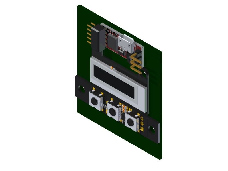
    So Simon's post on Facebook a week or so ago got me thinking and so I drew this up.

    Curt, Did you design the button board to fit on a HALO backplate? It fits Perfectly (if I have the dimensions right from Eagle)

    Looks like it'd be slightly thicker than the opening designed into the HALO but I haven't thought of any real ideas on how to solve that. I just thought it was cool that everything could fit.

    Team Akkadian Paintball Squad

    B.S. Mechanical Engineering UW-Platteville 2012

    Quote Originally Posted by neftaly
    Simon Stevens said that will be totally fine and nothing bad could ever happen. Ever.

  3. #273
    Insider Curt's Avatar
    Join Date
    Jun 2013
    Location
    Atlanta, GA
    Posts
    295
    Supports Inception Designs
    Supports Inception Designs
    As much as I'd like to take credit for thinking that far in advance and generically, it is 100% coincidence. not to worry, I'll have software that can drive loaders.. actually the stock Morlock software already does, if you have it in single-solenoid mode it runs the second solenoid as an 'accessory' channel.

  4. #274
    CAD Monkey skibbo's Avatar
    Join Date
    Apr 2013
    Location
    Milwaukee County, WI
    Posts
    1,059
    Supports Inception Designs
    Coincidences rule! It may be something like 1/16" off but its really minimal. I was hoping that it would drive loaders without much work, I'm pretty useless at programming. There's a ton of options w/the board which is great. I think I would rock a Halo again if it had a DNA/OLED board in it.

    Quote Originally Posted by Curt View Post
    As much as I'd like to take credit for thinking that far in advance and generically, it is 100% coincidence. not to worry, I'll have software that can drive loaders.. actually the stock Morlock software already does, if you have it in single-solenoid mode it runs the second solenoid as an 'accessory' channel.
    Team Akkadian Paintball Squad

    B.S. Mechanical Engineering UW-Platteville 2012

    Quote Originally Posted by neftaly
    Simon Stevens said that will be totally fine and nothing bad could ever happen. Ever.

  5. #275
    Insider new ion?'s Avatar
    Join Date
    Feb 2013
    Location
    Victoria, BC
    Posts
    1,296
    It actually sounds like he's saying it'll run your gun and your hopper off 1 board...

  6. #276
    thanks for the latest video, looks really nice, great to see how it all connects. For your next video can you show the connectors on the business end? (solenoid, microswitch, etc..)

    thanks!

  7. #277
    Insider Curt's Avatar
    Join Date
    Jun 2013
    Location
    Atlanta, GA
    Posts
    295
    Supports Inception Designs
    Supports Inception Designs
    sure, but I am working on the software mostly now, pop over to the project thread and prod them

  8. #278
    CAD Monkey skibbo's Avatar
    Join Date
    Apr 2013
    Location
    Milwaukee County, WI
    Posts
    1,059
    Supports Inception Designs
    Curt, trying to get a BOM together to make a daughter board for my Etha. Since I'm terrible at electronics and don't want to have to get a board made, I figured I could solder things together.

    Would something like this header work well? It seems like it would match based on the specs, and it's through hole which makes my life easier since SMD isn't my friend.
    Clicky for Link


    Also, going by this and your instructions and the other harness that I have,


    9 Volt Supply: 5 & 3
    Trigger: 8 & 3
    Eyes: 10 & 1 (emitter) and 4 & 3 (sensor)
    Solenoid: 5 & 7 (may need capacitor as well, but not sure)

    Thanks!
    Team Akkadian Paintball Squad

    B.S. Mechanical Engineering UW-Platteville 2012

    Quote Originally Posted by neftaly
    Simon Stevens said that will be totally fine and nothing bad could ever happen. Ever.

  9. #279
    Insider Curt's Avatar
    Join Date
    Jun 2013
    Location
    Atlanta, GA
    Posts
    295
    Supports Inception Designs
    Supports Inception Designs
    Quote Originally Posted by skibbo View Post
    Would something like this header work well? It seems like it would match based on the specs, and it's through hole which makes my life easier since SMD isn't my friend.
    Clicky for Link
    I can tell you for sure that exact component will work, I have a few in my workshop, ordered them weeks ago to make skeleton boards with

    Only downside is the price.

  10. #280
    Insider Curt's Avatar
    Join Date
    Jun 2013
    Location
    Atlanta, GA
    Posts
    295
    Supports Inception Designs
    Supports Inception Designs
    Quote Originally Posted by skibbo View Post
    9 Volt Supply: 5 & 3
    Trigger: 8 & 3
    Eyes: 10 & 1 (emitter) and 4 & 3 (sensor)
    Solenoid: 5 & 7 (may need capacitor as well, but not sure)
    Sensor will be 1&4, since pin 4 is pulled down, not up.

Posting Permissions

  • You may not post new threads
  • You may not post replies
  • You may not post attachments
  • You may not edit your posts
  •